Qt pro工程管理文件,本人认为是很好用的,语法简洁易懂,但是只能在QtCreator中使用,想用使用其它IDE比如Clion或者vs,CMakeLists是种通用的选择,另外QtCreator的调试功能跟粑粑一样。
一,思路
C++ 中编译,无外乎代码本身的头文件,源文件。三方库的头文件,库文件。Qt本身自带了UI文件和qrc资源文件。再就是宏定义或者路径的配置。
二,Qt pro文件
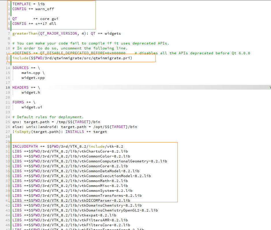
#需要的Qt模块
QT += core gui concurrent
greaterThan(QT_MAJOR_VERSION, 4): QT += widgets
#C++版本
CONFIG += c++17
#源文件
SOURCES += \
main.cpp \
util/DarkStyle.cpp
#头文件
HEADERS += \
3rd/snap7/include/snap7.h \
util/DarkStyle.h
#UI文件
FORMS += \
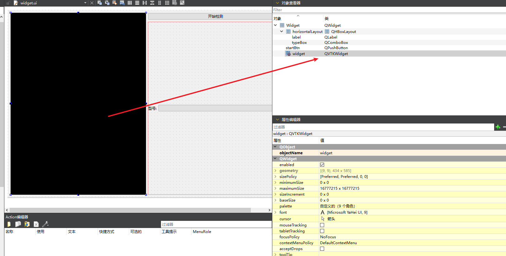
widget.ui \
widget/configwidget.ui
#翻译文件
TRANSLATIONS += \
consistency_zh_CN.ts
CONFIG += lrelease
CONFIG += embed_translations
# Default rules for deployment.
qnx: target.path = /tmp/$${TARGET}/bin
else: unix:!android: target.path = /opt/$${TARGET}/bin
!isEmpty(target.path): INSTALLS += target
#第三方库
INCLUDEPATH += $$PWD/3rd/snap7/include
LIBS += -L$$PWD/3rd/snap7/lib -lsnap7
win32:LIBS += -luser32
#资源文件
RESOURCES += \
app.qrc \
resources/darkstyle.qrc
#图标文件
RC_ICONS = app.ico
三,CMakeLists 文件
cmake_minimum_required(VERSION 3.20)
project(Consistency VERSION 1.0.0)

#C++ 版本
set(CMAKE_CXX_STANDARD 17)
set(CMAKE_INCLUDE_CURRENT_DIR ON)

#用来编译ui文件
set(CMAKE_AUTOMOC ON)
set(CMAKE_AUTORCC ON)
set(CMAKE_AUTOUIC ON)

#指定输出目录
set(OUTPUT_PATH ${CMAKE_CURRENT_SOURCE_DIR}/../bin)
set(CMAKE_RUNTIME_OUTPUT_DIRECTORY_DEBUG ${OUTPUT_PATH})
set(CMAKE_RUNTIME_OUTPUT_DIRECTORY_RELEASE ${OUTPUT_PATH})
set(CMAKE_RUNTIME_OUTPUT_DIRECTORY_RELWITHDEBINFO ${OUTPUT_PATH})
set(CMAKE_RUNTIME_OUTPUT_DIRECTORY_MINSIZEREL ${OUTPUT_PATH})

#需要加载的Qt模块
set(CMAKE_PREFIX_PATH "D:\\Qt\\5.15.2\\msvc2019_64\\lib\\cmake\\Qt5")
find_package(Qt5 REQUIRED COMPONENTS Core Gui Widgets Network Concurrent)

#头文件
set(HEADERS
    3rd/snap7/include/snap7.h
    util/DarkStyle.h
)

#源文件
set(SOURCES
    main.cpp
    util/DarkStyle.cpp
)

#UI文件
set(FORMS
    widget.ui
    widget/configwidget.ui
)

#资源文件
set(QRC_FILES
    app.qrc
	resources/darkstyle.qrc
)
qt5_add_resources(QRC_HEADERS ${QRC_FILES})

#第三方库
include_directories(${CMAKE_CURRENT_SOURCE_DIR}/3rd/snap7/include)
file(GLOB Snap7_LIB ${CMAKE_CURRENT_SOURCE_DIR}/3rd/snap7/lib/*.lib)

#生成可执行文件
add_executable(${PROJECT_NAME}
	${HEADERS}
	${SOURCES}
	${FORMS}
	${QRC_HEADERS}
		logo.rc
)

#链接对应的库
target_link_libraries(${PROJECT_NAME} Qt5::Core Qt5::Gui Qt5::Widgets Qt5::Network Qt5::Concurrent)
target_link_libraries(${PROJECT_NAME} User32.Lib)
target_link_libraries(${PROJECT_NAME}  ${Snap7_LIB})
四,备注
CMake 无法像pro那样处理图标文件,需要先新建一个rc文件,rc文件中指明icon文件,然后加载rc文件。
#logo.rc 文件
IDI_ICON1           ICON   DISCARDABLE  "app.ico"